

| 文字サイズ |
|---|

Type R25 & R15 Bestact Specification
The specifications for type R25 and R15 Bestact reed switches used in our Relays, Proximity Switches and Limit Switches.
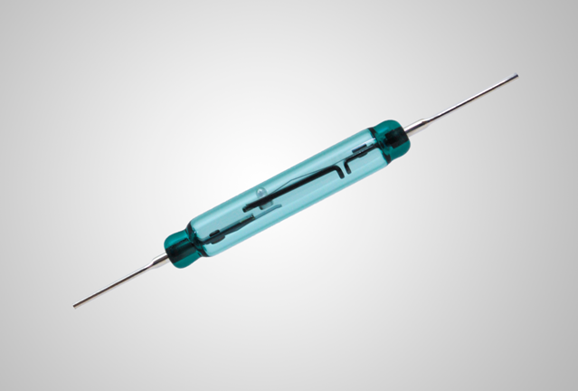
Medium capacity type: R25
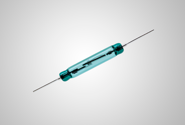
Large capacity type: R15
Application | Medium - Capacity Type | Large - Capacity Type | Remarks | ||
Type | R25 | R15 | ー | ||
Contact Arrangement | 1NO | 1NO | |||
Contact performance | Rated Insulation Voltage*1 | 250VAC | 250VAC | 50/60Hz | |
Rated Continuous Current*2 | 3A | 5A | ー | ||
Rated Operational Current*3 | AC | 240V 0.5A | 240V 1A | Inductive Load(50/60Hz) | |
DC | 115V 0.3A | 115V 0.5A,230V 0.2A | Inductive Load(Medium-capacity:L/R=40ms, Large-capacity : L/R=100ms) | ||
Maximum Making Current*4 | 240VAC 15A | 240VAC 30A | Power factor 0.3 to 0.4(50/60Hz) | ||
Maximum Breaking Current*5 | AC | 240V 15A | 240V 30A | Power factor 0.3 to 0.4(50/60Hz) | |
DC | 115V 0.5A | 115V 0.6A 230V 0.4A | Medium-capacity:L/R=40ms Large-capacity:L/R=100ms | ||
Minimum Operational Power Ratings*6 | 24V 1mA 5V 10mA* | 24V 1mA 5V 10mA* | Failure Rate λ₆₀=4.6×10-⁹(/time)or less *In circuit with photo coupler for digital application. | ||
Withstand Voltage Across Contacts | 500VAC for 1minute | 800VAC for 1minute | 50/60Hz | ||
Insulation Resistance | 10⁹Ω or greater | 10⁹ Ω or greater | with 500VDC Megger | ||
Initial Contact Resistance | 500mΩ or less | 500mΩ or less | 6VDC 1A | ||
Operating Characteristics | Pick-up Magnetmotive Force | 100 to 130AT | 180 to 230AT | Yaskawa standard coil is of 3000 turns, 33.5mm long, 10.5mm I.O. with 0.2mm dia. wire AT: A value, called ampere-turn, which indicates pick-up magnetmotive force and drop-out magnetmotive force | |
Drop-out Magnetmotive Force | 50AT or greater | 60AT or greater | |||
Operating Time | 4ms or less (Bounce Time not included) | 5ms or less (Bounce Time not included) | at 150% of pick-up ampare turn using standard coil (Equipped with a flywheel diode) | ||
Releasing Time | 2ms or less | 3ms or less | |||
Mechanical Life | Over 100,000,000 operations | Over 100,000,000 operations | ー | ||
Mechanical Performance | Vibration Resistance | 147m/s² {15G} | 196m/s² {20G} | 20 to 1000Hz | |
Shock Resistance | 196m/s² {20G} (980m/s² {100G}) | 392m/s² {40G} (980m/s² {100G}) | Value in parenthesis indicates breakdown G | ||
Terminal Drawing Force | 98N {10kgf} | 98N {10kgf} | ー | ||
Ambient Temperature | Operating Temperature | -50 to +150℃ | -50 to +150℃ | ー | |
Storage | -60 to +180℃ | -60 to +180℃ | ー | ||
Note: Ratings and specifications are defined according to IEC 62246-1.
*1. Rated insulation voltage is the voltage value which is the standard of insulation design and defined by the withstand voltage test.
*2. Rated continuous current is the current value which can be energized continuously without exceeding the allowable temperature rise under
the condition without breaking contacts.
*3. Rated operational current is the current value which is combined with a rated operational voltage and used in regulated conditions
(making/breaking current, switching frequency and electric switching durability).
At 240VAC, the current is set at 10 times this value upon making (PF: 0.6 to 0.7) and 1 times this value upon breaking (PF: 0.3 to 0.4).
Rated operational current 1A means 10A making and 1A breaking. At 115VDC, the current is set at 1 times making and 1times breaking
and indicated by inductive load (L/R=40ms and 100ms).
*4. Maximum making current is the current value which enables 10 times making at 240VAC and PF: 0.3 to 0.4 by referring to IEC 62246-1-1.
*5. Maximum breaking current is the current value which enables 10 times breaking at 240VAC and PF: 0.3 to 0.4 by referring to IEC 62246-1-1.
*6. Minimum operational power ratings are the values which can be surely energized under the regulated load conditions that the class of
contact reliability keeps a failure rate 0.005 (time/10⁶) or less.